简体中文
简体中文 


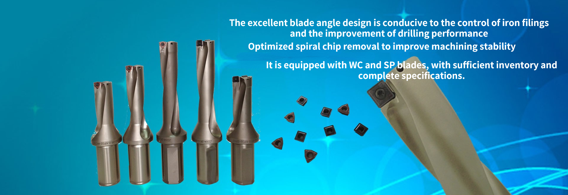

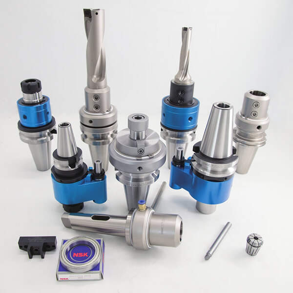
High speed oil path tool handle
There is automatic tool change at the end of the articleOil path tool handle installation tutorial and installation video
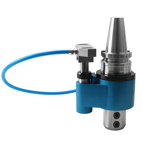
BT-OSL side fixed tool holder for high speed automatic tool change oil circuit

Specifications | L | l1 | l2 | l3 | D | d1 | d2 | S | T | Weight |
BT40-OSL16-150 | 150 | 48 | 25 | - | 82 | 16 | 49.5 | 65 | M12-1.75P | 3.10 |
BT40-OSL20-150 | 50 | 20 | 3.50 | |||||||
BT40-OSL25-165 | 165 | 56 | 15 | 20 | 25 | 3.50 | ||||
BT40-OSL32-165 | 60 | 32 | 7.80 | |||||||
BT50-OSL16-165 | 48 | 25 | - | 98 | 16 | 59 | 80 | M14-2.0P | 7.00 | |
BT50-OSL20-165 | 50 | 20 | M12-1.75P | 7.50 | ||||||
BT50-OSL25-165 | 56 | 15 | 20 | 25 | M16-2.0P | 7.50 | ||||
BT50-OSL32-165 | 60 | 32 | 9.05 | |||||||
BT50-OSL40-165 | 62 | 25 | 40 | M14-2.0P | 8.50 |
OSL reducer

Model | L | l1 | l2 | D | d1 | d2 | Weight |
OSL-20-16 | 54 | 48 | 5.5 | 30 | 16 | 20 | 0.07 |
OSL-25-16 | 60 | 35 | 25 | 0.19 | |||
OSL-25-20 | 56 | 20 | 0.15 | ||||
OSL-32-16 | 64 | 48 | 42 | 16 | 32 | 0.35 | |
OSL-32-20 | 56 | 20 | 0.32 | ||||
OSL-32-25 | 25 | 0.22 | |||||
OSL-40-16 | 74 | 48 | 50 | 16 | 40 | 0.57 | |
OSL-40-20 | 60 | 20 | 0.54 | ||||
OSL-40-25 | 25 | 0.45 | |||||
OSL-40-32 | 32 | 0.3 |
Eccentric sleeve

Model | L | d | D1 | D | weight |
20-25 | 48 | 20 | 41 | 25 | 0.19 |
25-32 | 60 | 25 | 49 | 32 | 0.21 |
32-40 | 65 | 32 | 58 | 40 | 0.23 |
40-50 | 76 | 40 | 68 | 50 | 0.24 |
High speed automatic tool changing oil path tool holder BT-OLER collet type

Specifications | L | l1 | S | D | Clamping range | Weight |
BT40-OLER16-160 | 160 | 90 | 65 | 82 | 1-10 | 3.80 |
BT40-OLER20-160 | 1-13 | 4.10 | ||||
BT40-OLER25-160 | 2-16 | 4.30 | ||||
BT40-OLER32-160 | 2-20 | 4.50 | ||||
BT50-OLER16-160 | 80 | 98 | 1-10 | 7.00 | ||
BT50-OLER20-160 | 1-13 | 7.10 | ||||
BT50-OLER25-160 | 2-16 | 7.20 | ||||
BT50-OLER32-160 | 2-20 | 7.30 | ||||
BT50-OLER40-160 | 4-26 | 7.50 |
ER / C water stop clamp

Model | d | Clamping range | d1 | D | L | l1 | l2 | l3 | Weight |
ER11C | 3-7 | 0.1 | 11 | 11.6 | 18 | 13.5 | 3.8 | 2.5 | 0.01 |
ER16C | 3-6 | 16 | 16.6 | 27.5 | 20.8 | 6.25 | 4 | 0.03 | |
6-10 | 0.5 | ||||||||
ER20C | 3-6 | 0.1 | 20 | 20.6 | 31.5 | 23.9 | 6.36 | 4.8 | 0.04 |
6-13 | 0.5 | ||||||||
ER25C | 3-6 | 0.1 | 25 | 25.6 | 34 | 25.9 | 6.66 | 5 | 0.05 |
6-16 | 0.5 | ||||||||
ER32C | 3-8 | 0.1 | 32 | 32.6 | 40 | 30.9 | 7.16 | 5.5 | 0.10 |
8-20 | 0.5 | ||||||||
ER40C | 10-26 | 0.1 | 40 | 40.6 | 46 | 34.9 | 7.66 | 7 | 0.25 |
12-34 | 0.5 |
适合于OER.OLER油路刀柄
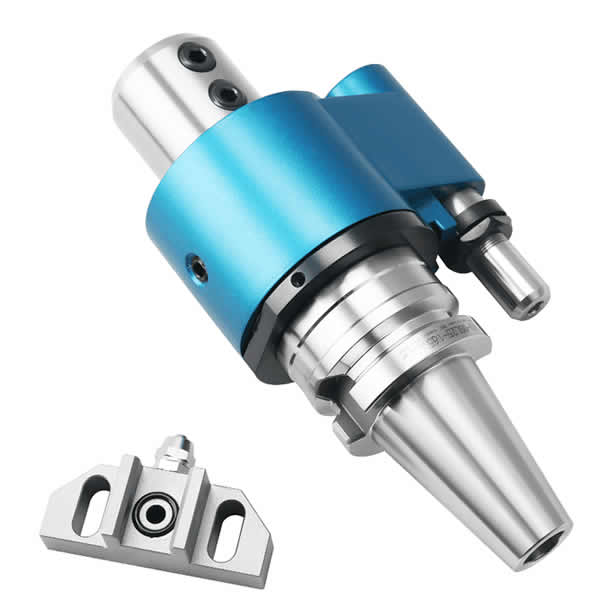
Position block

Model | L | l1 | l2 | l3 | l4 | C | D | Weight |
ST-18 | 27 | 9 | 18.1 | 17.2 | 18 | 46.2 | 18 | 0.29 |
It is suitable for most machining centers and generally does not need to be customized
Description of high-speed automatic tool change oil path tool handle:
Confirm the center distance s dimension before ordering
Bearing pressure 4MPa
Maximum speed: 3000rpm
Adjustment steps of tool handle of automatic tool change oil circuit
1. Confirm the distance from the tool handle center to the positioning column, BT40 = 65mm; BT50 = 80mm, and then compare with the distance from the spindle center of the machine tool to the fixed seat. If the distance is inconsistent, the customer shall adjust the position of the water inlet hole of the fixed seat by himself, and then install it (the fixed block is matched with the screw hole of the dust cover on the end face of the machine tool spindle).
2. Installation steps: A. first install the fixing block on the end surface of the machine tool, and connect the water inlet pipe with the positioning block. b. Installation of oil path tool handle: firstly loosen the M6 thread on the positioning key to make the positioning column move up and down freely (there is a spring under the positioning column), loosen the three M6 screws on the positioning ring to make it rotate freely with the oil path tool handle spindle (the screws cannot be loosened too much) C. lock the machine tool spindle, adjust the alignment between the keyway of the oil path tool handle spindle and the key position of the machine tool spindle, and adjust the angle of the positioning column at the same time, Align it with the water outlet hole of the positioning block. After pressing the positioning column, install the oil path tool handle on the machine tool spindle (after installation, check whether the positioning column is aligned with the water inlet of the positioning block, and the upper end surface of the positioning column needs to be closely fitted with the lower end surface of the positioning block to prevent water leakage. If it cannot be close, adjust the downward distance of the positioning block or change the thickness of the positioning block. d. Check again, turn on the cooling to check whether there is leakage and whether the housing is fastened when the main handle of the oil path tool handle rotates (manual rotation is recommended for the first use)
3. For the first use, turn on the rotating speeds s = 100, s = 300 and S = 500 respectively for tool handle running and (10 minutes). The maximum rotating speed during use shall not exceed 3000rpm

The oil path tool handle is suitable for the use of internal cooling tools, and can quickly realize the function of external cooling to internal cooling of the machine tool.